3. КОНСТРУКЦИИ В
РАЙОНАХ С СЕЗОННЫМ ПРОМЕРЗАНИЕМ
| ||||||||||||||||||||||||||||||||||||||||||||||||||||||||||||||||||||||||||||||||||||||||||||||||||||||||||||||||||||||||||||||||||||||||||||||||||||||||||||||||||||||||||||||||||||||||||||||||||||||||||||||||||||||||||||||||||||||||||||||||||||||||||||||||||||||||||||||||||||||||||||||||||||||||||||||||||||||||||||||||||||||||||||||||||||||||||||||||||||||||||||||||||||||||||||||||||||||||||||||||||||||||||||||||||||||||||||||||||||||||||||||||||||||||||||||||||||||||||||||||||||||||||||||||||||||||||||||||||||||||||||||||||||||||||||||||||||||||||||||||||||||||||||||||||||||||||||||||||||||||||||||||||||||||||||||||||||||||

|
среднепучинистых |
сильнопучинистых |
чрезмерно пучинистых |
|
1,0 |
1,5 |
2,0 |
Таблица 3
|
Значение коэффициента Ср в зависимости от толщины дорожной одежды (hод, м) и допустимой глубины промерзания земляного полотна (hпр(доп), см) |
|||||||||
|
hод = 0,5 |
hод = 1,0 |
hод = 1,5 |
hод = 2,0 |
||||||
|
hод(доп) |
hпр(доп) |
hпр(доп) |
hпр(доп) |
||||||
|
0 - 50 |
51 - 100 |
> 100 |
0 - 100 |
> 100 |
0 - 100 |
> 100 |
0 - 100 |
> 100 |
|
|
Песок пылеватый |
0,60 |
0,55 |
0,50 |
0,50 |
0,45 |
0,45 |
0,40 |
0,40 |
0,35 |
|
Супесь песчанистая |
0,70 |
0,65 |
0,60 |
0,60 |
0,55 |
0,55 |
0,50 |
0,50 |
0,45 |
|
Супесь пылеватая |
0,75 |
0,70 |
0,65 |
0,65 |
0,60 |
0,60 |
0,55 |
0,55 |
0,50 |
|
Суглинок легкий песчанистый, суглинок легкий пылеватый |
0,80 |
0,75 |
0,70 |
0,70 |
0,65 |
0,65 |
0,60 |
0,60 |
0,55 |
|
Суглинок тяжелый песчанистый, суглинок тяжелый пылеватый, глина |
0,85 |
0,80 |
0,75 |
0,75 |
0,70 |
0,70 |
0,65 |
0,65 |
0,60 |
Таблица 4
|
Номер изолинии на карте (см. рис. 10) |
Значение коэффициента Код при сроке службы дорожной одежды между капитальными ремонтами |
Значение коэффициента Кувл при типе увлажнения рабочего слоя земляного полотна |
|||
|
менее 10 лет |
10 лет |
20 лет |
1 тип увлажнения |
2 и 3 тип увлажнения |
|
|
I |
0,70 |
0,85 |
1,0 |
0,85 |
1,0 |
|
II |
0,70 |
0,85 |
1,0 |
0,65 |
1,0 |
|
III |
0,80 |
0,90 |
1,0 |
0,55 |
1,0 |
|
IV |
0,80 |
0,90 |
1,0 |
0,45 |
1,0 |
|
V |
0,80 |
0,90 |
1,0 |
0,40 |
1,0 |
|
VI |
0,80 |
0,90 |
1,0 |
0,35 |
1,0 |
|
VII |
0,80 |
0,90 |
1,0 |
0,30 |
1,0 |
|
VIII |
0,80 |
0,90 |
1,0 |
0,30 |
1,0 |
|
IX |
0,80 |
0,90 |
1,0 |
0,25 |
1,0 |
|
X |
0,80 |
0,90 |
1,0 |
0,25 |
1,0 |
уточняют по табл. 3 значение Ср в зависимости от hпр(доп);
вновь вычисляют значение выражения Lдоп / (СпучСр),
устанавливают по номограмме значение выражения Rод(тр) / (Код ´ Кувл), в зависимости от Lдоп / (СпучСр), типа увлажнения рабочего слоя земляного полотна и глубины залегания подземных вод (Нg) от низа дорожной одежды и номера изолинии на карте (см. рис. 10), которая проходит через рассматриваемый участок дороги;
вводят в выражение Rод(тр) / (КодКувл) значения коэффициентов Код и Кувл и вычисляют искомую величину Rод(тр).
При глубине залегания подземных вод на участке дороги, отличающейся от указанных на номограмме, нужно определять два значения Rод(тр): одно - при значении Нg на номограмме более, а другое - при значении Нg на номограмме менее глубины залегания подземных вод на участке. Искомое значение Rод(тр) устанавливают методом интерполяции между соответствующими величинами.
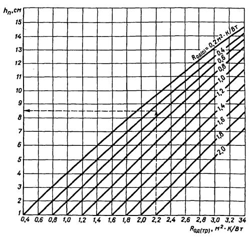
Рис. 12. График для определения необходимой толщины слоя пенопласта Styrofoam:
Rод(тр) - требуемое термическое сопротивление дорожной одежды; Rод(о) - термическое сопротивление дорожной одежды без слоя пенопласта
7. Устанавливают по графику (рис. 12) необходимую толщину слоя пенопласта hп, в зависимости от Rод(о) и Rод(тр).
При расположении рассматриваемого участка дороги между изолиниями на карте (см. рис. 10) определяют два значения hп, соответствующих этим изолиниям, искомую толщину теплоизолирующего слоя определяют методом интерполяции в зависимости от расстояния от рассматриваемого участка до одной из изолиний.
3.5. Расчет величины пучения грунта
Для определения по форм. 1 длины переходной зоны с переменной толщиной слоя пенопласта нужно знать величину hпуч(o) пучения грунта на «здоровом» участке дороги. Значение этой величины устанавливают по номограмме (см. рис. 11).
По сравнению с изложенным в п. 3.4 решается обратная задача. Искомым значением является Lдоп = hпуч(о) при известном значении Rод(тр), равном термическому сопротивлению дорожной одежды на «здоровом» участке дороги.
4. КОНСТРУКЦИИ В
РАЙОНАХ С ВЕЧНОМЕРЗЛЫМИ ГРУНТАМИ
4.1.
Принципы проектирования
В районах с вечномерзлыми грунтами устраивают дороги с теплоизолирующими слоями из пенопласта для того, чтобы обеспечить прочность и устойчивость земляного полотна. Это достигается благодаря сохранению грунтов естественного основания в твердомерзлом состоянии (1-й класс конструкций), а также этому же мероприятию в сочетании с сохранением грунтов насыпи в твердомерзлом состоянии (2-й класс конструкций).
Одним из условий обеспечения такого состояния грунтов является устройство земляного полотна зимой, когда основание насыпи промерзает на глубину более 30 см. Другим условием является устройство теплоизолирующего слоя из пенопласта, который предохраняет грунты от оттаивания в течение всего срока службы дороги. Обычно этот срок равен 30 годам.
Для сохранения грунтов в твердомерзлом состоянии в течение указанного срока нужно принимать в качестве расчетного года наиболее теплый год повторяемостью 1 раз в 30 лет. Для установления этого года нужно определить суммы положительных градусо-суток, отрицательных градусо-суток и их результирующее значение для каждого года за срок не менее 30 лет. По этим данным устанавливают искомый наиболее теплый год.
Толщину слоя пенопласта, необходимую для сохранения грунтов в твердомерзлом состоянии, определяют теплотехническим расчетом, в который включают среднемесячные значения температур воздуха, которые имели место в наиболее теплом году, а также для среднемноголетнего года. Расчеты проводят в 2 этапа. Вначале устанавливают значения температур в дорожной конструкции для среднемноголетнего года. Затем определяют значения температур для наиболее теплого года повторяемостью 1 раз в 30 лет. В этом случае в качестве начальных температур в дорожной конструкции принимают данные, полученные для среднемноголетнего года. При расчете температуры в конструкции нужно учитывать данные о температуре грунта естественного основания на глубине не менее 10 м от поверхности земли. Для определения температуры поверхности покрытия проезжей части и обочин, поверхности откосов и полосы отвода в расчет включают данные о солнечной радиации, скорости ветра и сезонных изменениях высоты и плотности снежного покрова.
4.2. Типы конструкций
Проектирование дороги проводят с учетом представленных на рис. 13 основных типов дорожных конструкций. Выбор конструкции проводят в зависимости от высоты насыпи и условий уплотнения грунта. Третий тип конструкции применяют при высоте насыпи (по оси проезжей части), равной толщине дорожной одежды. При большей высоте насыпи, но не более 2 м, применяют 1-й и 2-й типы конструкций. На участках дорог, проходящих в нулевых отметках, применяют 4-й тип конструкций.
Конструкцию 1-го типа следует применять при уплотнении песка, из которого устраивают насыпь, до значения, не менее 0,95 от максимальной плотности по ГОСТ 22733-90. В конструкции 2-го типа плотность песка не нормируется, так как этот грунт находится в твердомерзлом состоянии в течение всего периода эксплуатации дороги. Его плотность в насыпи должна быть равна максимальной плотности, которую можно достигнуть при уплотнении песка в зимний период.
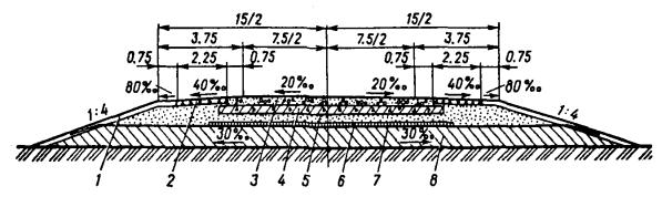
Рис. 13. Конструкции дорожной одежды и земляного полотна с теплоизолирующими слоями из пенопласта Styrofoam марки Floormate 500:
1 - пенопласт толщиной 8 см; 2 - пенопласт толщиной 6 см; 3 - пылеватый песок; 4 - мелкий песок; 5 - пескоцементная смесь; 6 - железобетонная плита; 7 - геотекстиль; 8 - пенопласт толщиной 14 см; 9 - пенопласт толщиной 13 см; 10 - трубчатая дрена
На рис. 13 приведены размеры дорожной конструкции на полуострове Ямал [6]. На проезжей части этой дороги предусматривается устройство покрытия из железобетонных плит толщиной 0,14 м на основании из пескоцементной смеси (10 % цемента) толщиной 0,25 м. Обочины укреплены той же пескоцементной смесью. Для обеспечения устойчивости откосов насыпи предусмотрены защитные прослойки из геотекстиля с укладкой на поверхность откосов мохорастительного слоя. Высота насыпи по бровке земляного полотна в конструкциях 1-го и 2-го типов составляет 1,5 м. Указанные на рис. 13 значения уклонов насыпи являются максимально допустимыми. Делать круче откосы нельзя, положе - можно.
При сооружении земляного полотна подготовительные работы (уборку снега, рубку и удаления леса и т.п.) следует проводить зимой с небольшим опережением основных земляных работ. Нижние слои насыпи следует отсыпать способом «от себя», а последующие - продольным способом.
Для устройства теплоизолирующего слоя нужно применять плиты со ступенчатой формой кромки. Принимая во внимание возможность подтопления в теплый период года мерзлой части насыпи в конструкции 2-го типа необходимо, чтобы вода не поступала через стыки между плитами в этот грунт. Для этого нужно, чтобы кромки плит пенопласта имели форму паз/выступ. Допускается применять плиты пенопласта со ступенчатой формой кромки с изоляцией стыков между плитами.
Плиты пенопласта следует укладывать с обеспечением равномерного их опирания на поверхность песчаного слоя. Чтобы не создавать сквозных швов, плиты пенопласта надо укладывать «вразбежку». Если плиты укладывают в два слоя, то швы нижележащего слоя нужно перекрывать вышележащими плитами. Плиты необходимо при укладке прикреплять к основанию штырями.
В летний период работу проводят в такой последовательности: доуплотняют слой мелкого песка, укладывают и уплотняют слой пескоцементной смеси, укладывают железобетонные плиты (см. рис. 13). Работы, выполняемые в теплый период времени, должны быть закончены за 2 - 3 мес. с момента перехода среднесуточной температуры воздуха через 0 °С. В противном случае может произойти оттаивание грунтов, которые должны находиться в мерзлом состоянии.
4.3. Расчет толщины слоя пенопласта
Программа для расчета на ЭВМ процессов тепло- и массообмена в дорожной конструкции должна учитывать сложное очертание расчетной области, наличие в пределах этой области различных видов грунтов и материалов, значительное число граничных условий в пределах расчетной области, фазовые переходы (выделение и поглощение скрытой теплоты в процессе промерзания-оттаивания), теплофизические свойства грунтов и материалов.
Грунтово-мерзлотные условия на трассе дороги должны характеризоваться следующими показателями: суммарной влажностью грунта, плотностью талого и мерзлого грунта, коэффициентом теплопроводности и объемной теплоемкостью талого и мерзлого грунтов, температурой льдообразования.
В расчет включают теплофизические характеристики слоев дорожной одежды, полученные по данным натурных измерений на существующих дорогах в рассматриваемом регионе. При отсутствии таких данных допускается включать в расчет табличные значения.
Необходимую толщину пенопласта определяют методом подбора, исходя из условия сохранения в твердомерзлом состоянии грунтов в течение всего периода эксплуатации дороги.
5. РАСЧЕТ ТОЛЩИНЫ МОРОЗОЗАЩИТНОГО СЛОЯ, ЗАМЕНЯЕМОГО ПЕНОПЛАСТОМ
Традиционным решением дорожной одежды в районах сезонного промерзания грунтов является ее устройство с морозозащитным слоем. Альтернативным решением является устройство дорожной одежды с теплоизолирующим слоем из пенопласта. Для оценки эффективности применения такой конструкции нужно знать толщину морозозащитного слоя, заменяемого пенопластом.
Сравнение конструкций с морозозащитным и теплоизолирующим слоями возможно при выполнении следующих условий. Эти конструкции должны удовлетворять нормативным требованиям по прочности, морозоустойчивости и дренированию, иметь одинаковые покрытие и основание. Разница между конструкциями заключается в том, что одна из них имеет морозозащитный слой, а другая - теплоизолирующий слой из пенопласта.
Исходя из этих условий определяют толщину морозозащитного слоя, заменяемого пенопластом, в следующем порядке.
1. Задаются толщиной морозозащитного слоя (hмз, м) и с учетом этого размера определяют толщину дорожной одежды (hод, м) и расстояние до уровня подземных вод (Hg, м).
2. Устанавливают требуемое термическое сопротивление дорожной одежды. Расчет приведен в п. 3.4. Разница только в значениях показателя пучинистости грунта Спуч, которые нужно выбирать по табл. 5.
Значения показателя Спуч зависят от местонахождения рассматриваемого участка дороги. Это связано с влиянием глубины и скорости промерзания на пучение грунта. Чем больше скорость, тем меньше поступает воды из талого грунта в мерзлый и тем меньше пучинистость грунта.
Таблица 5
|
Номер изолинии на карте (см. рис. 10) |
Значение показателя Cпуч для грунтов |
||
|
среднепучинистых |
сильнопучинистых |
чрезмерно пучинистых |
|
|
I |
1,40 |
2,10 |
2,80 |
|
II |
1,25 |
1,85 |
2,50 |
|
III |
1,10 |
1,65 |
2,20 |
|
IV |
1,00 |
1,50 |
2,00 |
|
V |
0,90 |
1,35 |
1,80 |
|
VI |
0,80 |
1,20 |
1,60 |
|
VII |
0,70 |
1,05 |
1,40 |
|
VIII |
0,60 |
0,90 |
1,20 |
|
IX |
0,50 |
0,75 |
1,00 |
|
X |
0,40 |
0,60 |
0,80 |
3. Определяют значение толщины морозозащитного слоя, м, заменяемого пенопластом:
hмз = (Rод(тр) - Rод(о))lмз, (3)
где Rод(тр) - требуемое термическое сопротивление дорожной одежды, м2×К/Вт; Rод(о) - термическое сопротивление дорожной одежды без морозозащитного или теплоизолирующего слоя, м2×К/Вт; lмз - коэффициент теплопроводности морозозащитного слоя, равный среднеарифметическому значению коэффициентов теплопроводности материала слоя в талом и мерзлом состоянии, Вт/(м×К).
4. Сравнивают значение hмз, полученное по форм. 3, с заданной величиной hмз. При разнице между ними не более 5 см расчет закончен. В противном случае нужно задаться новым значением hмз и повторить расчет.
ПРИЛОЖЕНИЕ 1
ТЕХНИЧЕСКАЯ ХАРАКТЕРИСТИКА ПЕНОПЛАСТА
Для устройства теплоизолирующих слоев на дорогах применяют пенопласт Styrofoam марки FLOORMATE 500. Данные о физико-механических свойствах этой марки пенопласта представлены в табл. 6.
Лист пенопласта имеет длину 1250 мм, ширину 600 мм, толщину 30, 40, 50, 60, 80, 100 мм. Форма кромки - ступенчатая.
Пенопласт не поддается воздействию карбоната натрия, гидроокиси кальция, натрия хлорида (поваренная соль), органических веществ (гумус, сапропель), бактерий природного происхождения. При наличии в грунте кислот, щелочей, органических удобрений и других веществ, не перечисленных выше, следует оценивать устойчивость пенопласта в каждом конкретном случае по составу и концентрации этих веществ.
Таблица 6
|
Нормативный документ, регламентирующий метод определения показателя |
Единица измерения |
Значение показателя |
|
|
Плотность исходная |
DIN 53420 ГОСТ 17177-87 |
кг/м3 |
38/40 |
|
Теплопроводность при температуре 10 °С |
DIN 52612 |
Вт/(м×К) |
0,027/0,025 |
|
То же при температуре 20 °С |
Вт/(м×К) |
0,028 |
|
|
Водопоглощение |
DIN 53434 ГОСТ 17177-87 |
об, % |
0,20/0,45 |
|
Прочность на сжатие при 5 % деформации |
ГОСТ 17177-87 |
Н/мм2 |
0,51 |
|
То же при 10 % деформации |
DIN 53421 |
Н/мм2 |
0,50 |
|
Предел прочности при изгибе |
ГОСТ 17177-87 |
Н/мм2 |
0,72 |
|
Модуль упругости |
DIN 53421 |
Н/мм2 |
20 |
|
Капиллярность |
- |
- |
0 |
|
Огнестойкость - группа воспламеняемости |
ГОСТ 3002 |
- |
В1 - трудновоспламеняем |
|
Диапазон рабочих температур |
- |
°С |
От минус 50 до плюс 75 |
Пенопласт следует предохранять от воздействия нефтяных продуктов (бензин, керосин и др.), органических растворителей (бензол, ацетон и др.). Не допускается укладка непосредственно на пенопласт «горячего песка» и других нагретых материалов, обработанных органическими вяжущими материалами.
При длительном хранении (более 5 сут.) под открытым небом плиты пенопласта следует предохранять от прямого солнечного воздействия. Не допускается складирование пенопласта вблизи открытого огня.
ПРИЛОЖЕНИЕ 2
ПРИМЕРЫ РАСЧЕТА
Пример 1. Определить необходимую толщину теплоизолирующего слоя из пенопласта на участке дороги, проходящей в районе г. Москвы, при неблагоприятных грунтово-гидрологических условиях. На этом участке подземные воды залегают на глубине 0,5 м от поверхности земли. Грунт естественного основания - суглинок легкий пылеватый, который относится к чрезмерно пучинистым грунтам. Из этого же грунта возводится земляное полотно. Высота насыпи 1,65 м.
По условиям обеспечения прочности и дренирования нужно устраивать конструкцию дорожной одежды, состоящей из асфальтобетонного покрытия толщиной 0,20 м (плотный асфальтобетон - 0,05 м, пористый асфальтобетон - 0,15 м); основания толщиной 0,30 м из известнякового щебня и дренирующего слоя толщиной 0,20 м из среднезернистого песка. Срок службы дорожной одежды (период между капитальными ремонтами) - 10 лет. Допустимая величина пучения 4 см.
Расчет толщины слоя пенопласта проводят согласно п. 3.4. По карте (см. рис. 10) номер изолинии, которая проходит через рассматриваемый участок дороги - V. По формуле 2 Rод(о) = 0,46 м2×К/Вт. По табл. 2 Спуч = 2,0. По табл. 3 - Ср = 0,76 для суглинка легкого пылеватого при hод = 0,7 м и hпр(доп) = 0 - 50 см. По табл. 4 Код = 0,90 и Кувл = 0,95. По номограмме (см. рис. 11) hпр(доп) = 72 см при Lдоп / (СпучСр) = 2,6 и Нg = 1,45 м. По табл. 3 Ср = 0,73 при hод = 0,7 м и hпр(доп) = 72 см. По номограмме (см. рис. 11) Rод(тр) = 0,81 м2×К/Вт при Lдоп / (СпучСр) = 2,7, Hg = 1,45 м, Код = 0,90, Кувл = 0,95.
По графику (см. рис. 12) определяют искомую толщину слоя пенопласта: hп = 1,8 см при Rод(о) = 0,46 м2×К/Вт и Rод(тр) = 0,81 м2×К/Вт. Учитывая минимальные размеры плиты (см. прилож. 1), принимается толщина слоя пенопласта 3 см.
Пример 2. Определить толщину морозозащитного слоя из песка, заменяемого пенопластом, для указанной дороги в районе г. Москвы. Расчет проводят согласно п. 5. Исходные данные те же, что и ранее. Задаемся величиной hмз = 0,95 м. В этом случае hод = 1,65 м и Hg = 0,5 м. По табл. 3 Ср = 0,64 при hод = 1,65 м и hпр(доп) = 0 - 100 см. По табл. 4 Код = 0,90 и Кувл = 0,95. По табл. 5 Спуч = 1,80. По номограмме (см. рис. 11) hпр(доп) = 62 см при Lдоп / (СпучСр) = 3,5 см и Hg = 0,5 м. По табл. 3 Ср = 0,64 при hод = 1,65 м и hпр(доп) = 62 см. По номограмме (см. рис. 11) Rод(тр) = 0,92 м2×К/Вт при Lдоп / (СпучСр) = 3,5 см, Нg = 0,5 м, Код = 0,90, Кувл = 0,95. По форм. 3 hмз = 0,92 м. Расчет закончен, так как разница между заданным и полученным значениями hмз составляет 3 см, что менее 5 см. Получаем, что толщина морозозащитного слоя, заменяемого пенопластом, составляет 0,95 м.
СПИСОК ЛИТЕРАТУРЫ
1. Строительные нормы и правила 2.05.02-85. Автомобильные дороги. М.: ЦИТП Госстроя, 1986. 56 с.
2. Пособие по проектированию методов регулирования водно-теплового режима верхней части земляного полотна (к СНиП 2.05.02-85) / Под ред. В.И. Рувинского. М.: Стройиздат, 1989. 97 с.
3. Рувинский В.И. Оптимальные конструкции земляного полотна - 2-е изд., перераб. и доп. М.: Транспорт. 1992. 240 с.
4. Рувинский В.И. Эффективность применения пенопласта в дорожном строительстве России. М.: Транспорт, 1996. 72 с.
5. Технические указания по устройству дорожной одежды с теплоизолирующим слоем из пенопласта стайрофоум на дорогах г. Москвы. М.: Мосинжпроект, 1997. 25 с.
6. Конструктивные решения дорожной одежды и земляного полотна с теплоизолирующими слоями из пенопласта стайрофоум на дороге Промбаза-База дирекции на полуострове Ямал. Под ред. В.И. Рувинского. Надымгазпром, 1998. 78 с.
V.I. RUVINSKY
Manual
for construction
of STYROFOAM
heat-insulating
layers
on roads in Russia
V.I. Ruvinsky. Manual for Construction of Styrofoam Heat-Insulating layers on Roads in Russia. - M. Transport, 2000, 71 p.
The Manual shows problems which can be solved by means of plastic foam «Styrofoam» manufactured by the Dow Chemical Company. Compared to the traditional solutions of road structures, the use of plastic foam makes it possible to reduce the frost-protective layer thickness, to decrease the embankment height and cut depth, to use the soil of increased moisture content, to improve the evenness and durability of pavements.
It is shown that in some cases plastic foam can only provide the strength and frost resistance of road structures.
The results of investigations on choosing a required grade of plastic foam for installing the heat-insulating layers in road structures are given.
The principles of designing road structures with the plastic foam heat-insulating layers are shown.
The road structures with the plastic foam heat-insulating layers in regions of a seasonal freezing of soils and in those of permafrost are presented.
The Manual presents nomograms for determining the required thickness of a plastic foam layer and for designing the frost-protective layer replaced by plastic foam.
The brochure is intended for engineers engaged on the road design and construction and it may help teaching staff and students of transport institutes of higher education. The nomograms of the brochure may be used for specifying the required thickness of a plastic foam layer in the airfield pavements.
CONTENTS
INTRODUCTION
The Manual has been worked out in elaboration of the requirements of SNIP (Construction Norms and Rules) on the construction of heat-insulating layers [1]. The Manual makes it possible to solve quite a number of problems of road construction on the provision of the road pavement strength and frost resistance and of the subgrade stability in the regions of a seasonal freezing of soils and in those of ever frozen soils. The problems are proposed to be solved by means of plastic foam heat-insulating layers.
The Manual represents structures with plastic foam-insulated layers and methods for their design. Some of them can replace traditional road structures, others are the only possible solutions of the problem of providing the road pavement strength and frost resistance and the subgrade stability. The Manual allows to appreciate an efficiency of using structures with plastic foam insulating layers as compared to traditional structures, including the design of the thickness of the frost-protective layer replaced by plastic foam.
The Manual proposes recommendations for choosing a plastic foam grade for installing the heat-insulating layers. At present there are data of long-term tests of plastic foam on the roads in Russia only for the Styrofoam grade produced by the Dow Chemical Company. The tests showed that the above-said plastic foam could be used for the construction of heat-insulating layers on the roads in Russia [4].
Appropriate specifications and standards (1 - 6) allowing to construct roads with the Styrofoam heat-insulating layers have been developed in Russia. Styrofoam has been certificated by the Ministry of Construction of Russian Federation.
The Manual presents nomograms making it possible to determine the required thickness of a plastic foam layer on the roads in the regions of a seasonal soil freezing. The nomograms may be used for specifying the required thickness of a plastic foam layer in the airfield pavements. In this case the allowable value of soil heave should be included into computation according to the standards for airfields.
The Manual may be used not only for road building in Russia but in the countries of CIS (Commonwealth of Independent States) and in the Baltic States as well.
1. PROBLEMS SOLVED BY MEANS OF PLASTIC FOAM
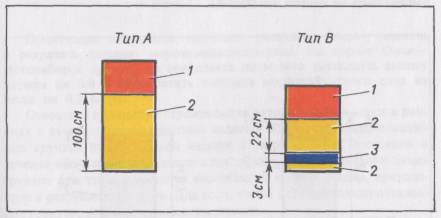
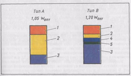
1.1. Decrease in the thickness of a frost-protective layer
In regions of a seasonal freezing of soils, the value of their heaving under the road pavement should not exceed allowable values [2]. To meet those requirements, the frost-protective layers are constructed from conforming sands, sand-gravel mixtures, gravel, soils treated with binders and other nonfrost-susceptible heaving materials. On the section of unfavourable soil-hydrological conditions, the thickness of a frost-protective layer can reach 1 m and more. On such sections, it is difficult to provide the required amount of conforming soils and materials for the construction of frost-protective layers. In many regions, there are no such soils and materials. The haul distance of conforming sands totals tens and hundreds of kilometers.
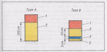
Fig. 1. Road pavement structures of the same frost resistance under conditions of Moscow:
1 - surfacing and base courses of road pavement; 2 - sand; 3 - Styrofoam
The installation of a plastic foam heat-insulating layer makes it possible to decrease the thickness of a frost-protective layer significantly or to exclude it completely.
Figure 1 shows the road pavement structures including the frost-protective layer made from sand (type A) and the heat-insulating layer made from plastic foam (type B). The structures meet the requirement as per strength and frost resistance under conditions of Moscow [5].
1.2. Decrease in an embankment height
In regions of a seasonal soil freezing the embankment height must have such value lest the overwetting of soil of a subgrade working layer should occur. The embankment height depends on the soils, which are included in the subgrade working layer [1]. The thickness of the working layer is assumed to be equal to 2/3 of a freezing depth but not less than 1.5 m from the pavement surface.
The plastic foam heat-insulating layer makes it possible to reduce the working layer thickness at the expense of decreasing the freezing depth. Due to this, it is possible to exclude unfavourable soils from the working layer, which permits to lower the requirements for the minimum height of embankment.
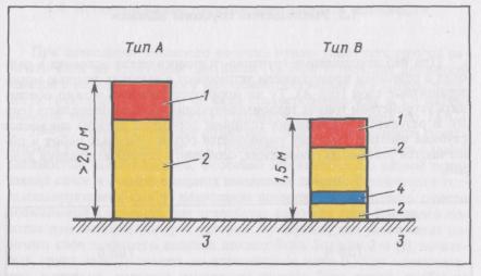
Figure 2 shows the minimum values of embankment heigts which have to be constructed in the Arkhangelsk region on the sections where ground waters are on the level of the ground surface. In case of a traditional road pavement the embankment height made from fine sand or sandy loam should be not less than 2.0 m (type A). In case of a road pavement structure with the heat-insulating layer preventing soil freezing below the ground surface, the embankment height should be not less than 1.5 m (type B).

Fig. 2 Minimum values of embankment heights in the Arkhangelsk region when constructing the traditional road pavement (Type A) and the road pavement with plastic foam preventing soil freezing below the ground surface (Type B):
1 - road pavement; 2 - fine sand or sandy loam; 3 - silt sandy loam and silt loam; 4 - Styrofoam

Fig. 3. Minimum values of embankment heights on the Yamal peninsula when constructing the traditional road pavement (Type A) and the road pavement with plastic foam preventing soil thawing below the ground level (Type B):
1 - road pavement; 2 - fine sand; 3 - ice saturated soil; 4 - Styrofoam
The use of plastic foam makes it possible to reduce the embankment height and, at the same time, to decrease the frost-protective layer thickness. On the Omsk - Novosibirsk highway, the use of plastic foam allowed to reduce the embankment height by 0.9 m and to decrease the thickness of the frost-protective layer made from sand by 0.3 m [4].
The basic principle of constructing roads in the regions of perennially frozen soils consists in the preservation of ice-saturated soils under the embankment bottom in a hard-frozen state during the whole period of road operation. When thawing such soils lose their bearing capacity, and there appears a subsidence resulting in road damage.
In order to prevent soil thawing, one constructs a high embankment. The embankment height can be reduced at the expense of installing the plastic foam heat-insulating layers. Figure 3 presents minimum values of embankment heights which have to be constructed on the Yamal peninsula, with the 30-year service life of the road [6].
In the case of building conventional subgrade structures from fine sand, the embankment height must be more than 2.0 m (type A). If the subgrade is built with the plastic foam heat-insulating layers, the embankment height must be 1.5 m (type B), proceeding from the condition of non-snow-drifting the road.
1.3. Decrease in a cut depth
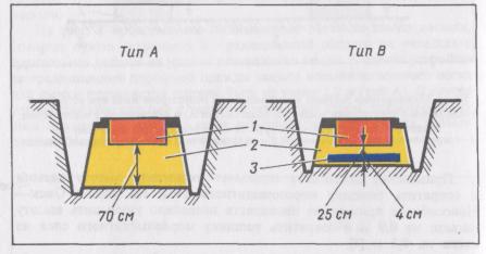
Under unfavourable soil-hydrological conditions in the regions of a seasonal soil freezing, thick frost-protective layers (type A) are installed in the cuts. The same frost-resistance can be provided by means-of installing thin plastic foam heat-insulating layers (type B). Owing to reducing the road pavement thickness, the cut depth is decreased. As a result, the amount of earthworks is cut down and the conditions of their fulfilling become easier, especially in the rain period.
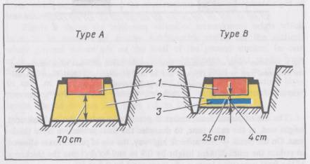
Fig. 4. Subgrade structures in the cuts on the Omsk - Novosibirsk road when constructing the traditional road pavement (Type A) and the road pavement with Styrofoam (Type B):
1 - surfacing and base courses of road pavement; 2 - medium-grained sand; 3 - Styrofoam
Figure 4 shows the subgrade structures in the cuts on the Omsk - Novosibirsk highway section, from the design kilometer 38 + 500 to km 76 + 515. The highway has been designed according to the standards of the 1st category. The road pavement in the structures of types «A» and «B» meets the requirements as per strength and frost resistance.
The required amount of plastic foam is 840 m3 per 1 km of road. At the expense of installing a heat-insulating layer the required quantity of conforming sand (i.e. non-frost susceptible sand with the filtration coefficient higher than 2 m/day) is reduced by 11920 m3 per 1 km of road and the amount of earthworks is decreased by 24400 m3 - 35400 m3 (depending on the cut depth) per 1 km of road.
1.4. Use of soils of increased moisture content
When constructing the subgrade, it is necessary to compact the working layer soils to the required density [1]. When constructing the road pavement with an asphalt surfacing or a cement concrete pavement, the soil density must be not less than 0.98 and 1.0, respectively, of the maximum density in accordance with the standard compaction method of GOST 22733-90 (State Standard). Compaction like that is possible only when the moisture content of soil is close to the optimum one (Wopt).
It is usually difficult to provide the construction with such moisture content, especially in spring after snow thawing and in autumn in the rain period.
The use of the plastic foam heat-insulating layers makes it possible to apply soils of increased moisture content for constructing the subgrade working layer fulfilling three conditions. First, the type of the subgrade working layer should be the first or the second one [1]; second, the soil should be compacted to the density not lower than 0.95 of the maximum one and, third, the plastic foam thickness must have such value lest a soil freezing under the road pavement should occur.
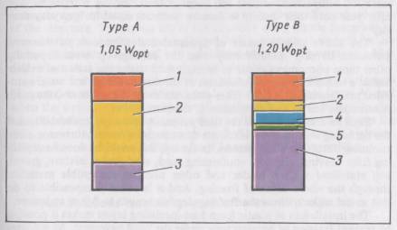
Fig. 5. Allowable values of moisture content of heavy silt loam at which the soil can be compacted to the specified values when constructing the traditional road pavement (Type A) and the road pavement with plastic foam (Type B):
1 - surfacing and base courses of road pavement; 2 - sand; 3 - heavy silty loam; 4 - Styrofoam; 5 - geotextile
Under these conditions the soil frost heaving does not take place and only its shrinkage in summer period occurs. As a result, the soil is compacted additionally to the maximum density and even more [4].
Figure 5 shows maximum values of moisture content of heavy silty loam, at which it is possible to use this soil for constructing the subgrade working layer in case of a traditional road pavement structure with the asphalt surfacing (type A) and in case of installing the plastic foam heat-insulating layer in the structure (type D).
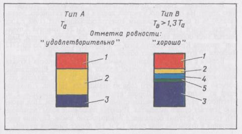
1.5. Improvement of the pavement durability and evenness
During the road operation in the regions of a seasonal freezing, the all-round-year process of varying the density and moisture content of the heaving soils takes place. The process consists of the four periods: swelling in autumn, frost heaving in winter, soil subsidence when thawing in spring, and shrinkage when drying in summer. All-round-year variations of the density and moisture content are repeated during the whole service life of the structure. In this case, as a result of the subsidence and shrinkage of soils for a spring summer period, there can or cannot occur a restoration of their initial density achieved in constructing the road. In the latter case, losses of compaction of soils will occur if frost heaving is repeated year after year until their density in summer becomes equal to «everyday density» [3].
The above said processes of upheaval and subsidence of the road pavement develop nonuniformly over the carriageway area. Especially often these phenomena occur in spring, when under the action of vehicle traffic a nonuniformity of subsidence of the discompacted and water-saturated soil intensifies. As this takes place, the more the soil heave, the more nonuniform heaval and subsidence of the carriageway.
Such an annual effect on the road pavement influences its durability and the surfacing evenness. To eliminate frost heaving means to increase the surfacing durability and evenness. In theory, this could by done be replacing frost heaving soils with conforming sand, sand-gravel mixture, gravel, soil stabilized with a binder and other nonfrost-susceptible materials through the whole depth of freezing. And it is actually impossible to do this in the regions where the freezing depth amounts to 3.0 m and more.
The installation of plastic foam heat-insulating layers makes it possible to prevent freezing of heaving soils under the road pavement. As a consequence of this, the basic factor of losses of compaction of the subgrade working layer soils is removed.
The density of the non-swelling and weakly-swelling soils actually does not change during road operation. The moisture content of soils compacted to the specified values does not also change. Under these conditions the bearing capacity of the working layer soils does not practically change from season to season. Only owing to this factor the surfacing durability increases approximately by 30 % as compared to the traditional solution of the structure. The service life of the structure using plastic foam will be considerably longer than the indicated value because there will be no annual nonuniform upheaval and subsidence of the road pavement, which determines to a large extent the structure durability.
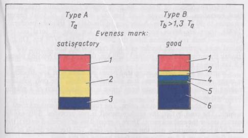
Fig. 6. Indices of the surfacing service life and evenness when constructing the traditional road pavement (Type A) and the road pavement with plastic foam (Type B):
1 - surfacing and base courses of road pavement; 2 - sand; 3, 6 - soil; 4 - Styrofoam; 5 - geotextile
Figure 6 shows the relationship between the service life of surfacings (T, years) in case of a traditional road pavement structure (type A) and when the structure is built with the plastic foam layer preventing freezing of soils of the subgrade working layer (type B). The Figure also shows the data concerning a surfacing evenness on the Omsk - Novosibirsk highway. The measurements were fulfilled after 12 years of road service [4].
1.6. Solutions feasible only with the use of plastic foam
One of the tasks of the road maintenance service consists in eliminating frost heaves on the existing road network. Frost heaves are called the road pavement and subgrade deformations, which are displayed in winter in forming frost mounds and in a surfacing evenness failure and in the period of thawing, when vehicles run, in a road pavement damage due to decreasing the strength of the overwetted soils.
Under conditions of Russia the frost heaves significantly complicate road operation. On separate road sections, the length of frost heaves amounts to 30 % and more. According to the data of Irkutskgiprodornii (1998), there are seven heaving places 6.5 km long in total on the Tyumen - Omsk road section from the 248th km to the 297th km. On the Baikal road section, the border of the Krasnoyarsky krai - the city of Irkutsk from the 1689th km to the 1712th km, there exist 10 heaving places 6.8 km long in total.
Control of frost heaves using traditional methods is of low efficiency in many cases, and, sometimes, it is absolutely useless. The only solution making it possible to eliminate frost heave is the installation of a plastic foam heat-insulating layer.
Figure 7 shows one of such cases. The road is on the embankment 1 m high. The land is flat, the surface runoff is not provided. Silty sandy loam is under the embankment. There is ground water (perched water), the level of which coincides with the ground surface. The freezing depth in the open field is over 1.5 m. There are frost heaves on the road.
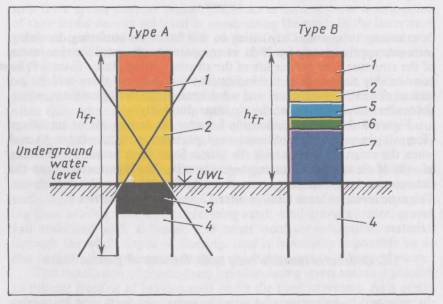
Fig. 7. Road pavement with a frost-protective layer (Type A) and a plastic-foam heat-insulating layer (Type B) considered when solving the problem of removing frost heaves from the road:
1 - surfacing and base courses of road pavement; 2 - sand; 3 - gravel; 4 - silly sandy loam; 5 - Styrofoam; 6 - geotextile; 7 - soil of the existing embankment; hfr - freezing depth
The reconstruction of the heaving road section provides for building the road pavement 0.5 m thick. If an additional frost-protective layer is installed, its thickness should be more than 0.5 m (type A). Under such conditions, the road pavement bottom is located below the ground surface in the area of perched water.
To provide the required durability of the structure, it is necessary to drain water from the road pavement courses and the upper layers of the subgrade. These requirements cannot be fulfilled. It is impossible to drain water in the flat land, when a portion of the frost-protective layer is below the ground water level. Therefore, under the above said conditions the frost-protective layer for eliminating frost heaves should not be installed. The frost-protective layer made from granular materials has much more disadvantages. It will be filled with water below the ground level, as a result of which the bearing capacity of the granular material will decrease. The frost-protective layer filled with water will not eliminate frost heaving, for there will occur ice formation.
The structure including a plastic foam heat-insulating layer (type B) has no drawbacks indicated and allows to remove frost heaves from the roads.
In regions of ever frozen soils, there may be such situations when it is impossible to manage without using plastic foam. One of these situations is a forced construction of the subgrade in the low fill due to the territory relief [6]. If the plastic foam heat-insulating layer is not installed, there will occur a thawing of ice-saturated soils under the embankment bottom, which will result in a road failure. The use of plastic foam makes it possible to prevent a thawing of soils and to save the road.
2. Determination of the required plastic foam grade
2.1. Conditions of the plastic foam performance in the structure
Plastic foam in the structure is subjected to the effect of force and natural factors. The action of short-term repeated loads resulted from vehicle traffic causes compression deformation at bending of plastic foam. The effect of natural factors on the plastic foam layer is manifested in freezing and thawing, in moistening and drying, in nonuniform heaval and subsidence of the heat-insulating layer. Under conditions of Russia, the temperature gradient through the depth of the plastic foam layer amounts to 1.5 deg/cm and more.
The action of loads from vehicle traffic takes place under conditions when the upper part of the plastic foam layer is in a thawed state and the lower one is frozen, and vice versa. Under such combined action of force and natural factors, it is difficult to model the plastic foam performance in the structure. The main mechanism of a plastic foam failure is the material fatigue. The basic criterion for specifying a plastic foam grade is the results of field observations.
2.2. Tests on roads
In 1983 - 1999 according to the indication of Ministry of Construction, the tests of Styrofoam of grade HI-50, were conducted on the Omsk - Novosibirsk highway (region of seasonal freezing) and on the Urengoy - 185 road (region of perennially frozen soils).
The section of the Omsk - Novosibirsk highway with the Styrofoam heat-insulating layers is in the area of the town of Chulym [4]. This area is characterized by severe freezing winters, hot summers and unfavourable soil hydrological conditions. According to Hydrometeorological Center, the air temperature can be as low as -50 °C in winter and as high as +38 °С in summer. In the period of testing plastic foam the sum of negative degree-days was from 1133 to 2575 for one winter.
The road on the Styrofoam-insulated section runs across the territory without surface runoff. The perched water is found at the depth of 0.5 to 1.7 m from the ground surface. The subgrade made from light silty clay is in the embankment 1.65 m high. The same is under the embankment bottom. The road pavement of the trial section has a cement concrete pavement (Fig. 9). Styrofoam insulation has been in the road pavement for 12 years. In order to assess the durability of Styrofoam, the plastic foam samples were taken from the trial section of Omsk - Novosibirsk highway. The samples were tested by the Test Center «Stroypolymertest». The results of the test are presented in Table 1.
The data of Table 1 make it possible to conclude that the Styrofoam properties remained actually the same during the road service, with the exception of some degree of its compression during the construction of the road pavement.
The test results showed that Styrofoam of HI-050 grade could be applied for installing heat-insulating layers on the roads. At present the nomenclature of plastic foams produced by The Dow Chemical Company has changed. Instead of HI-50 grade, the Floormate 500 grade should be taken.
Table 1
|
Method of Determination |
Values of indices of physico-mechanical properties of plastic foam |
||
|
|
|
Initial |
Final |
|
Density, kg/m3 |
DIN 53420 GOST 15588-86 |
38 |
43,1 |
|
Compression strength at 10 % linear deformation, MPa (N/mm2) |
DIN 53421 GOST 15588-86 |
0,40 |
0,48 |
|
Modulus of elacticity, MPa (N/mm2) |
DIN 53421 GOST 23404-86 |
15 |
19,2 |
|
Thermal conductivity at 10 °C, W/(m×K) |
DIN 52612 |
0,027 |
... |
|
Thermal conductivity in dry state at 20 °C, W/(m×K) |
GOST 7076-87 |
... |
0,0286 |
|
Thermal conductivity in water-saturated state at 20 °C and moisture content of 4.6 % by weight, W/(m·K) |
GOST 7076-S7 |
... |
0,0301 |
|
Water absorption of entire board, % by volume |
DIN 53434 |
0,2 |
... |
|
Water absorption after 300 freezing and thawing cycles, % by volume |
DIN 53434 |
1,0 |
... |
|
Water absorption during 24 hours, % by volume |
GOST 15588-86 |
... |
0,53 |
3. Structures in the seasonal freezing regions
3.1. Principles of designing
The road pavement structure should meet specifications as per strength, frost resistance and drainage [1].
The requirements as per frost resistance consist in that the value of soil heaving under the road pavement not exceed allowable values. In Russia, the value of soil heaving on the road, Lall, is assumed to be equal to 3 cm in case of a cast-in - place cement concrete pavement, 4 cm - in case of a precast pavement, 4 cm - in case of an asphalt surfacing of the road pavement of capital type, 6 cm - in case of an asphalt surfacing of the road pavement of lightened type. For roads of international class the allowable value of soil heave under the road pavement must not exceed 2 cm.
The allowable value of soil heave is specified by a customer for constructing the road and this value should not be higher than the value presented above. The lower is the allowable value of soil heave, the better is the surfacing evenness during road operation and the longer is the road operation and the longer is the road pavement service life.
An installation of the plastic foam heat-insulating layer permits to reduce the value of heave at the expense of decreasing the depth of subgrade freezing. The required thickness of the plastic foam insulating layer should be determined for the road pavement structure complying with the requirements for strength and drainage. The thickness of the plastic foam layer is specified with taking into account a service life of the road pavement between capital repairs, type of moistening the subgrade working layer [1], depth of the occurrence of underground waters from the bottom of the road pavement, and soils. When soils of various types occur within the freezing depth, it is necessary to consider in the design the parameters of the soil with the highest degree of heaving.
The Styrofoam-insulated layer should be placed at the depth at least 0.5 m from the road surface lest the frequency of glazed frost formation on the road surface should exceed 10 % as compared to the section with a traditional road pavement structure [3].
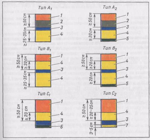
3.2. Structures for new construction
When designing, there may be 6 basic types of solution for road structures with the Styrofoam heat-insulating layer. The choice of a necessary solution depends on the road pavement structure designed on the strength and drainage conditions, and on its cost. Figure 8 shows the types of solutions for the road pavement.
When the heaving soils thaw, there occurs their subsidence followed by squeezing out water. This water should be drained from under the road pavement. In this connection, in the structure of type «C2», it is necessary to use plastic foam boards with edges of straight shape in order that water could flow into the draining layer through the slits between the boards.
The structure of type «B» is built with the use of plastic foam boards the edges of which are of stepped shape. The rest of the structures shown in Figure 8 are built with the use of plastic foam boards which have one or other shape of the edges depending on the source of water inflow and conditions of water drainage.
The thickness of a draining layer depends on the filtration coefficient of sand. If it is equal to 3 m/day and more, the minimum thickness of a draining layer in the structure of type «C2» is 20 cm, if the filtration coefficient is less than 3 m/day, the thickness of a draining layer amounts to 25 cm.
Figure 9 shows a cross section of the road pavement structure of type «C1» (sizes are given in meters). The Omsk - Novosibirsk highway has such a structure, [4].
The width of the plastic foam-insulated layer should be greater than that of the carriageway by 0.5 m (0.5 m) - 1.5 m (2.0 m) for insulating the soils under the road pavement against the cold effect from the side of shoulders. The values in brackets are assumed in case of preventing soil freezing under the road pavement. Peculiarities of fulfilling construction jobs are as follows.
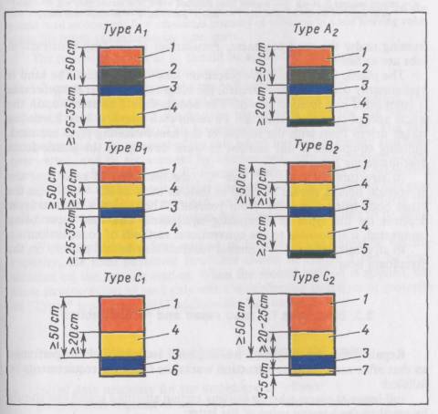
Fig. 8. Basic types of road pavement structures with the Styrofoam heat-insulating layer used in new construction:
1 - surfacing and base courses of road pavement; 2 - cement concrete base course; 3 - Styrofoam; 4 - sand draining layer; 5 - geotextile interlayer against silting; 6 - geotextile draining interlayer; 7 - sand levelling course
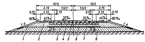
Fig. 9. Cross section of the road structure, Type C:
1 - grass sown on the 0.15 m layer of soil; 2 - crushed stone (0.1 m) bound with bitumen (1.5 l/m2); 3 - cement concrete (0.24 m); 4 - crushed stone stabilized with 6 % of cement (0.21 m); 5 - sand (0.20 m); 6 - Styrofoam (0.10 m); 7 - «dornit» geotextile; 8 - soil (light silty clay)
The plastic foam boards are placed on sand or geotextile. The sand is preliminarily compacted and levelled, the subgrade soil under the geotextile is compacted and levelled as well. The boards should be rested upon the whole area of sand and geotextile. To retain each board, at least 2 wooden stakes driven flush with the surface of the heat-insulating layer are used. Building equipment is not allowed to work directly on the plastic foam heat-insulating layer.
In structures of types «B» and «C», the first layer of sand over the Styrofoam boards should be filled at least as thick as 0.2 - 0.25 m in the dense body using a method «from yourself. The thickness of sand layer depends on the types of compacting equipment. The sand layer being compacted, it is possible to use conventional methods of construction.
In structures of type «A», cement concrete may be laid directly on the Styrofoam boards.
3.3. Structures for road repair and reconstruction
Repair (reconstruction) of a heaving road section should be performed so that after completing construction works the following requirements be fulfilled:
soil heave at places where a heaving section adjoins a sound one should be equal to the heaving value of the latter;
soil heave in the middle part of a repaired (reconstructed) road section should not exceed an allowable value for a specified type of the pavement;
an intensity of variation in the soil heaving value along the length of a repaired (reconstructed) road section should not exceed an allowable value.
The fulfilment of these requirements increases the road pavement durability and allows to prevent pavement cracking at places of adjoining a sound road section due to the difference in soil heave values.
On the approach to a sound road section, a transition zone with a plastic foam layer of variable thickness must be built. The length of the zone is determined by formula:
![]() (1)
(1)
where Itz = length of the transition zone, m; Lall = allowable value of soil heave on the repaired (reconstructed) road section, cm; Hh(о) = soil heaving value on the sound road section, cm; Itz = admissible intensity of variation in a soil heaving value along the length of the transition zone, cm/m.
The following values of Itz should be applied in the design:
0.1 cm/m - when laying the concrete pavement;
0.2 cm/m - when laying the asphalt concrete pavement.
On the heaving section, the soil loses its density and is overwetted. The repair (reconstruction) of this section begins with restoring the bearing capacity of the subgrade. This is performed by two methods. The first method includes the removal of the soil, which has lost its density and been overwetted, and its replacement by another soil, with a subsequent compaction to a standart density. The second method involves the placement of a geotextile reinforcing interlayer under the road pavement. In this case the removal of soil is not required, and it is only needed to perform the soil compaction up to the maximum magnitude corresponding to its moisture content.
When applying the first method of improving the subgrade bearing capacity, the road pavement structures shown in Figure 8 can be constructed on the heaving section. When the second method is applied, the same structures can be used only with the reinforcing interlayer of geotextile of «Typar» type, grade 3857 additionally laid under them.
3.4. Design of the plastic foam layer thickness
Initial data necessary for the design are as follows:
geographical location of the road section under consideration;
road pavement structure (name and thickness of layers) without a heat-insulating layer, which is required according to the strength and drainage conditions;
type of moistening the subgrade working layer (type 1, 2 or 3) and depth of the ground water occurrence from the road pavement bottom;
name of the subgrade soil.
The design of the heat-insulating layer (hf), cm, is carried out in the following order:
1. The number of isoline that runs along the section considered is determined from the map (Fig 10). When the road section is between two isolines, the numbers of both of them are found.
2. Thermal resistance of the road pavement without a heat-insulating layer (Rp(0) m2×K/W) is computed:
![]() (2)
(2)
where nр = number of structural layers of the road pavement without the heat-insulating layer; hp(i) = thickness of a separate layer, m; lp(i) - coefficients of the heat-conductivity of separate layers in a frozen state.
The design should include actual measured values of lp(i). In the absence of such data the tabulated values lp(i) [2] may be used in the design. These values for some materials are given below: 1.74 W/(m×K) for cement concrete; 1.40 W/(m×K) for dense asphalt concrete; 1.25 W/(m×K) for porous asphalt concrete; 1.86 W/(m×K) for crushed granite; 1.39 W/(m×K) for crushed limestone; 2.10 W/(m×K) for sand-gravel; 2.00 W/(m×K) for sand.
3. The soil heaving index, Ch, is determined from Table 2. The following soils are referred to the medium heaving ones: sandy loam, light sandy clay loam, heavy sandy clay loam, clay.
The highly heaving soils are as follows: silty sand, silty sandy loam, heavy silty loam. The extremely heaving soils are as follows: silty sandy loam with a sand particle content at least 20 % by weight and light silty loam.
When dealing with soils of specific types and needing a higher accuracy, the heaving index should be determined from the results of soil test in compliance with GOST 28622-90.
4. The coefficient Cp that takes into account the influence of the weight of the road pavement and subgrade frozen courses on the soil heave value is assessed. This coefficient is found from Table 3 regarding a thickness of the road pavement (hp, m) and an allowable freezing depth of the subgrade (hfr(all), cm).
When values of the road pavement thickness are lower or higher than those given in Table 3, the value of Cp should be established by interpolating between appropriate values.
At first, one should assume the value of Cp that corresponds to an allowable freezing depth of the subgrade in a range of 0 to 50 (100).
The value of coefficient Km must be reduced by 5 % if the road is located in south subzone II of the road - climatic zone, by 10 % if the road is located in road - climatic zone III and by 15 % if the road is located in road - climatic zone IV [1].
5. Using Table 4, the following coefficient values are found:
Kp = coefficient taking account of the road pavement service life;
Km = coefficient considering the type of moistening the subgrade working layer.
6. The required thermal resistance of the road pavement (Rp(req), m2×K/W) is determined from the nomogram (Fig. 11). Proceed as follows:
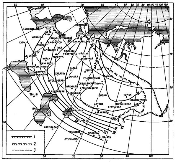
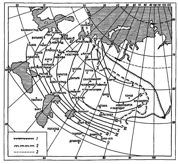
Fig. 10. Map with isolines for determining the required values for thermal resistance of road pavement:
I - Х - numbers of isolines; 1 - boundary of the continuous occurrence of perennially frozen soils; 2 - ditto, of the insular occurrence (up to 25 m in depth); 3 - Arctic Circle

Fig. 11. Nomogram for determining the required thermal resistance of road pavement Rp(req) at La / (ChСp) equal to 0 to 6 cm and from 6 to 30 cm:
I - Х - isoline numbers on the map (Fig. 10); 1 - design curve for types 1 and 2 of moistening the subgrade working layer
compute the value of Lall / (ChСp);
determine the value of hfr(all) from the nomogram depending on Lall / (ChСp), type of moistening the subgrade working layer, and depth of ground water occurrence, (Hl, m) from the road pavement bottom;
define more exactly the value of Cp depending on hfr(all) using Table 3;
estimate again the value of Lall / (ChСp);
determine the value of Rp(req) / (KpKm) from the nomogram depending on Lall / (ChСp), type of moistening the subgrade working layer, and depth of ground water level (Hg) from the road pavement bottom as well as the number of the isoline on the map (Fig. 10) that goes through the road section considered;
Table 2
Table 3
|
Values of coefficient Cp depending on the road pavement thickness (hp, m) and allowable depth of subgrade freezing (hfr(all), cm) |
|||||||||
|
hp = 0,5 |
hp = 1,0 |
hp = 1,5 |
hp = 2,0 |
||||||
|
hfr(all) |
hfr(all) |
hfr(all) |
hfr(all) |
||||||
|
0 - 50 |
51 - 100 |
> 100 |
0 - 100 |
> 100 |
0 - 100 |
> 100 |
0 - 100 |
> 100 |
|
|
Siltysand |
0,60 |
0,55 |
0,50 |
0,50 |
0,45 |
0,45 |
0,40 |
0,40 |
0,35 |
|
Light sandy loam |
0,70 |
0,65 |
0,60 |
0,60 |
0,55 |
0,55 |
0,50 |
0,50 |
0,45 |
|
Silty sandy loam |
0,75 |
0,70 |
0,65 |
0,65 |
0,60 |
0,60 |
0,55 |
0,55 |
0,50 |
|
Light sandy clay loam, Light silty clay loam |
0,80 |
0,75 |
0,70 |
0,70 |
0,65 |
0,65 |
0,60 |
0,60 |
0,55 |
|
Heavy sandy clay loam, Heavy silty clay loam, Clay |
0,85 |
0,80 |
0,75 |
0,75 |
0,70 |
0,70 |
0,65 |
0,65 |
0,60 |
Table 4
|
Isoline number on the map (see Fig. 10) |
Values of coefficient Kp for road pavement service life between major repairs |
Values of coefficients Km for the type of moistening the subgrade working layer |
|||
|
Less than 10 years |
10 years |
20 years |
type 1 |
types 2 and 3 |
|
|
I |
0,70 |
0,85 |
1,0 |
0,85 |
1,0 |
|
II |
0,70 |
0,85 |
1,0 |
0,65 |
1,0 |
|
III |
0,80 |
0,90 |
1,0 |
0,55 |
1,0 |
|
IV |
0,80 |
0,90 |
1,0 |
0,45 |
1,0 |
|
V |
0,80 |
0,90 |
1,0 |
0,40 |
1,0 |
|
VI |
0,80 |
0,90 |
1,0 |
0,35 |
1,0 |
|
VII |
0,80 |
0,90 |
1,0 |
0,30 |
1,0 |
|
VIII |
0,80 |
0,90 |
1,0 |
0,30 |
1,0 |
|
IX |
0,80 |
0,90 |
1,0 |
0,25 |
1,0 |
|
X |
0,80 |
0,90 |
1,0 |
0,25 |
1,0 |
introduce the value of the coefficients of Kp and Km into expression Rp(req) / (KpKm) and calculate the desired value of Rp(req).
If the depth of ground water occurrence on the road section differs from the depth shown on the nomogram, it is necessary to determine two values of Rp(req.): when the value of Hg on the nomogram is higher than the depth of ground water occurrence on the mentioned road section and when it is lower than the depth of ground water occurrence. The required value of Rp (req.) is determined by interpolation between relevant values.
7. The required thickness of the plastic foam layer (hf, cm) is found from the plot in Figure 12 depending on Rр(0) and Rp(req).
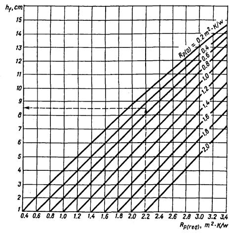
Fig. 12. Plot for determining the required thickness of the Styrofoam layer:
Rр(req) - required thermal resistance of road pavement; Rp(0) - thermal resistance of road pavement without the plastic foam layer
When the section under consideration is between the isolines on the map (Fig. 10), two values of hf corresponding to these isolines are evaluated. The desired thickness of the heat-insulating layer is established by the interpolation method in dependence on the distance from the section examined to one of the isolines.
3.5. Computation of the soil heave value
To compute by formula 1 the transition zone including the plastic foam layer of variable thickness, it is necessary to know the value of soil heave hh(0) on the sound road section. This value is found from the nomogram in Figure 11.
As compared to the above described in item 3.4, in this case one solves the reverse problem. The desired value is Lall = hh(0) at the known value of Rp(req) that is equal to the thermal resistance of the sound section of the road pavement.
4. Structures for permafrost regions
4.1. Design principles
In the regions of perenially frozen soils, roads are built with heat-insulating layers of plastic foam in order to provide the subgrade strength and stability. This is achieved through maintaining soils of the natural foundation in a hard-frozen state (structures of type 1); ditto plus maintaining the embankment soils in a hard frozen state (structures of type 2).
One of the conditions for ensuring such state of soils is the construction of subgrade in winter when the embankment foundation is frozen to a depth of more than 30 cm. Another condition is the installation of the heat-insulating layer of plastic foam that protects soils against thawing during the period of road life. This period is usually about 30 years.
To retain soils in a hard-frozen state during the above period, the warmest year of frequency once for 30 years should be assumed as the design one. To determine this year, it is required to find a sum of positive degree-days, a sum of negative degree-days and their resulting value for each year during a period of at least 30 years. From these data the desired warmest year is established.
The thickness of the plastic foam layer, needed to retain soils in a hardfrozen state, is estimated through a heat-engineering computation.
The computation includes average monthly air temperatures that occurred in the warmest year. The same is performed for the average year of multi-year period. The computation is done in two stages. At first, temperatures in the road structure are established for the average year of the multi-year period. Then temperatures are determined for the warmest year of frequency once for 30 years. In this case, the data obtained for the average year of the multi-year period are assumed as initial temperatures in the road structure. When computing the temperature in the structure, consideration should be given to the temperature data for the natural foundation soil at a depth of not less than 10 m from the ground surface. In order to evaluate the temperature on the carriageway and shoulder pavement surface as well as on the slope and right-of-way surface, the data on solar radiation, wind velocity, and snow cover height and density are introduced into computation.
4.2. Types of structures
The road design is performed on the basis of the main types of the road structures presented in Figure 13. The choice of a structure is made with regard for an embankment height and soil compaction conditions. The structure of type 3 is applied when the embankment height (along the carrigeway axis) is equal to the road pavement thickness. In case of a higher embankment, but not higher than 1 m, the structures of types 1 and 2 are used. The structures of type 4 are employed on the road sections passing through a datum level.
The structure of type 1 should be applied provided it is possible to compact the sand, which is used for the embankment construction, to a density at least 0.95 from the maximum one according to GOST 22733-90. With the structures of type 2, the sand density is not specified because this soil will be in a hard-frozen state during the whole period of road operation. Its density in the fill should be equal to the maximum one that can be reached when the sand is compacted in winter.
Figure 13 presents the dimensions of the road structure used on the Yamal peninsula [6]. On the carriageway of this road, the pavement of reinforced concrete slabs 0.14 m thick is laid over the base course of the sand-cement mixture (10 % of cement) 0.25 m thick. The shoulders are strengthened by the same sand-cement mixture. To provide the stability of the embankment slopes, the use is made of geotextile protective interlayers, with laying a moss-vegetative cover on the slope surface. In the structures of types 1 and 2, the embankment height along the subgrade edge is 1.55 m. The embankment gradients given in Figure 13 are the maximum admissible ones. The steeper slopes are impermissible while the flatter ones can be built.
Fig. 13. Structures of road pavement and subgrade with heat-insulating layers of Styrofoam of Floormate 500 grade:
1 - plastic foam layer 8 cm thick; 2 - plastic foam layer 6 cm thick; 3 - silty sand; 4 - fine sand; 5 - sand-cement mix; 6 - reinforced concrete slab; 7 - geotextile; 8 - plastic foam layer 14 cm thick; 9 - plastic foam layer 13 cm thick; 10 - pipe drain
Site preparation (snow removal, felling and clearing operations, etc.) for the subgrade construction should be carried out in winter a little ahead of main earthworks. The lower courses of the embankment must be built by the method «from yourself» whereas the next layers - by the longitudinal method.
The heat-insulating layer should be constructed of boards with the edge of a stepped shape. Taking into consideration a probability of flooding the frozen part of the embankment in the structure of type 2 during the warm period of the year, it is necessary to prevent water infiltration into the soil through the joints between the boards. That is why the edges of the plastic foam boards should be of groove-and-tongue type. The plastic foam boards with the stepped edges are admissible to use with isolating the joints between them.
The plastic foam boards should be installed so as to provide their uniform resting on the surface of the sand course. In order to avoid the through joints, the boards must be laid in a staggered way. When two layers of the boards are installed, joints of the lower layer should be overlapped with the overlying boards. When installing, the boards should be connected to the base course by pins.
The work sequence in summer was as follows: additional compaction of fine sand, laying and compaction of the sand-cement mix course, and placement of the reinforced slabs (Fig. 13). Works performed in the warm period of time must be completed within not more than 2 - 3 months since the time when there occurs a transition of the average daily air temperature through 0 °C. Otherwise, the soils that must be in a frozen state can thaw.
4.3. Design of the plastic foam layer thickness
The computer program for the computation of heat-and mass-exchange of the road structure should take into consideration: a complex contour of the structure, the presence of different types of soils and materials, a considerable number of boundary conditions within the design area, phase transitions (latent heat releasing and absorption during freezing-thawing), thermal-and-physical properties of soils and materials.
The soil-frost conditions along the route of a road should be characterized by the following indices: total moisture content of the soil, density of the thawed and frozen soil, coefficients of thermal conductivity and volumetric thermal capacity of the thawed and frozen soils, and temperature of ice-formation.
The design includes the thermal-and-physical characteristics of the road pavement layers obtained from the data of field measurements on the road in the area considered. In the absence of such data, the tabulated values may be used in computation.
The required thickness of the plastic foam layer is found by the method of selection proceeding from the condition of retaining the soils in a hard-frozen state during the whole period of road service.
5. DESIGN OF THE FROST-PROTECTIVE LAYER REPLACED BY PLASTIC FOAM
The conventional solution for the road structure in the regions of seasonally frozen soils is its construction with the frost-protective layer. An alternative solution is to build the road pavement with the heat-insulating layer of plastic foam. To evaluate the efficiency of the use of such structure, it is necessary to know the thickness of the frost-protective layer replaced by plastic foam.
A comparison between the structure with the frost-protective layer and that with the heat-insulating one is possible under the observance of the conditions listed below. Both of these structures should meet the specifications as to strength, frost-resistance, and drainage. They both should have the same surfacing and base courses. The only difference between them is that one of the structures will include the frost-protective layer whereas the other - the heat-insulating one of plastic foam.
On the basis of the above conditions the thickness of the frost-protective layer replaced by plastic foam is determined as follows:
1. The frost protective layer thickness (hfp, m) is given, and with taking it into account the road pavement thickness (hp., m) and the distance to the ground water level (Hg, m) are determined.
2. The required value of the road pavement thermal resistance is assessed. The computation is performed in the same way as it is described in 3.4. The only difference is in the values of the soil heave index (Ch) that should be taken from Table 5.
Table 5
|
Isoline number in the map (see Fig. 10) |
Values of Сh for soils: |
||
|
Medium heaving |
Highly heaving |
Extremely heaving |
|
|
I |
1,40 |
2,10 |
2,80 |
|
II |
1,25 |
1,85 |
2,50 |
|
III |
1,10 |
1,65 |
2,20 |
|
IV |
1,00 |
1,50 |
2,00 |
|
V |
0,90 |
1,35 |
1,80 |
|
VI |
0,80 |
1,20 |
1,60 |
|
VII |
0,70 |
1,05 |
1,40 |
|
VIII |
0,60 |
0,90 |
1,20 |
|
IX |
0,50 |
0,75 |
1,00 |
|
X |
0,40 |
0,60 |
0,80 |
As Table 5 shows, the values of Ch are dependent on the location of the road section under examination, which is connected with the influence of the freezing depth and rate on the soil heave. The higher the rate of freezing, the less water inflows from the thawed soil into the frozen one and the less is the soil heave.
3. A value of the thickness of the frost-protective layer replaced by plastic foam (hfp, m) is estimated:
hfp = (Rp(req) - Rp(0))lfp, (3)
where Rp(req) - required thermal resistance of the road pavement, m2×K/W; Rp(0) - thermal resistance of the road pavement without the frost-protective and heat-insulating layers, m2×K/W; lfp - coefficient of thermal conductivity of the frost-protective layer equal to the arithmetical mean value of thermal conductivity coefficients of the layer material in thawed and frozen states W/(m×K).
4. One compares the value of hfp, obtained on formula 3, with the prescribed value of hfp. If the difference between these values does not exceed 5 cm, the design is completed. Otherwise a new value of hfp must be given and the design repeated.
APPENDIX 1
ENGINEERING CHARACTERISTICS OF PLASTIC FOAM
For building the road heat-insulating layers the plastic foam «Styrofoam» of FLOORMATE 500 grade is applied. Table 6 presents physical-and-mechanical properties of the plastic foam of this grade.
Dimensions of the plastic foam board: length - 1250 mm; width - 600 mm; thickness - 30, 40, 50, 60, 80, 100 mm. The edge shape is stepped.
The plastic foam is resistant to the action of sodium carbonate, calcium hydroxide, sodium chloride (common salt), organic matters (humus, sapropel), bacteria of natural origin.
When acids, alkali, organic fertilizers and other substances, not listed above, are present in the soil, it is required to evaluate the stability of the plastic foam individually for a particular composition and concentration of these matters.
Table 6
|
Parameters |
Method of determination |
Unit |
Value |
|
Initial density |
DIN 3420 GOST 17177-87 |
Kg/m3 |
38 40 |
|
Thermal conductivity at 10 °C |
DIN 52612 GOST 7076-87 |
W/(m×K) |
0,027 0,025 |
|
Thermal conductivity at 20 °C |
GOST 7076-87 |
W/(m×K) |
0,028 |
|
Water absorption |
DIN 53434 GOST 17177-87 |
% by volume |
0,20 0,45 |
|
Compression strength at 5 % deformation |
GOST 17177-87 |
N/mm2 |
0,51 |
|
Compression strength at 10 % deformation |
DIN 53421 |
N/mm2 |
0,50 |
|
Ultimate flexural strength |
GOST 17177-87 |
N/mm2 |
0,72 |
|
Modulus of elasticity |
DIN 53421 |
N/mm2 |
20 |
|
Capillarity |
- |
- |
0 |
|
Fire resistance (flammability group) |
GOST 3002 |
- |
BI (highly fire-resistant) |
|
Range of service temperatures |
- |
°C |
-50 to +75 |
The plastic foam should be protected against the action of petroleum products (gasoline, kerosine, etc.), organic solvents (benzene, acetone, etc.). Laying «hot sand» or other heated materials treated with organic binders directly over the plastic foam is impermissible.
In case of the long-term outdoor storage (more than 5 days) the plastic foam boards should be kept from direct sunlight. It is not allowable to stack up the plastic foam boards near the open flame.
APPENDIX 2
DESIGN EXAMPLES
1. It is required to determine the desired thickness of the plastic foam heat-insulating layer on the section of the road passing through the area of the city of Moscow under unfavourable soil-hydrological conditions. On this section, the ground water level is at a depth of 0.5 m from the ground surface. The soil of the natural foundation is light silty loam, which is referred to the extremely heaving soils. The subgrade is built from the same soil. The embankment height is 1.65 m.
Proceeding from the conditions of strength and drainage the road pavement structure should consist of: asphalt concrete surfacing 0.20 m thick (dense asphalt - 0.05 m; porous asphalt 0.15 m); crushed limestone base 0.30 m thick that includes the 0.20 m drainage course of medium-sized sand. The service life of the road pavement (service period between capital repairs) is 10 years.
Allowed value of heaving is 4 cm.
The thickness of the plastic foam layer is computed according to item 3.4. From the map in Figure 10, the number of isoline that passes through the road section considered is V. From formula 2, Rp(0) = 0.46 m2×K/W. From Table 2, Ch = 2.0. From Table 3, Cp = 0.76 for light silty loam at hp = 0.7 and hfr(all) = 0 - 50 cm. From Table 4, Kp = 0.90 and Km = 0.95. From the nomogram in Figure 11, hfr(all) = 72 cm at Lall / (ChCp) = 2.6 and Hl = 1.45 m. From Table 3, Cp = 0.73 at hp = 0.7 m and hfr(all) = 72 cm. From the nomogram in Figure 11, Rp(req) = 0.81 m2×K/W at Lall / (ChCp) = 2.7, Hl = 1,45 m, Kp = 0.90, Km = 0.95.
From the plot in Figure 12, the desired thickness of the plastic foam layer hf = 1.8 cm at Rp(0) = 0.46 m2×K/W and Rp(req) = 0.81 m2×K/W. Taking account of the minimum dimensions of the board (Appendix 1), the thickness of the plastic foam layer is assumed to be 3 cm.
2. It is required to determine the thickness of the frost-protective layer replaced by plastic foam for the above mentioned road in the vicinity of Moscow. The computation is performed according to item 5. The original data, excluding the value of Ch, are the same as above: Rp(0) = 0.46 m2×K/W, Kp = 0.90, Km = 0.95. We are set by value hfp = 0.95 m. Then hp = 1.65 m, Hg = 0.5 m. From Table 3, Cp = 0.64 m at hp = 1.65 m and hfr(all) = 62 cm. From Table 5, Ch = 1.80. From the nomogram in Figure 11, hfr(all) = 62 cm at Lall / (ChCp) = 3.5 and Hg = 0.5 m. From the nomogram in Figure 11, Rp(req) = 0.92 m2×K/W at Lall / (ChCp) = 3.5, Hl = 0.5 m, Kp = 0.90, Km = 0.95. From formula 3, hfp = = 0.92 m.
The calculation is finished since the difference between the prescribed values and the obtained ones is 3 cm, i.e. less than 5 cm. We obtain that the thickness of the frost protective layer replaced by plastic foam is 0.95 m.
REFERENCES
1. Construction Norms and Rules 2.05.02-85. Avtomobilnye dorogi. Moscow TsITP Gosstroy USSR, 1986.
2. Manual for Design Methods, Control of the Water-and-Temperature Regime in the Upper Part of the Subgrade /to SNIP 2.05.02-85/ edited by V.I. Ruvinsky, M Stroyizdat Publishers, 1989.
3. Ruvinsky V.I. Optimum Subgrade Structures. 2d edition, revised and enlarged. M.: Transport Publishers, 1992.
4. Ruvinsky V.I. Efficiency of the Use of Plastic Foam «Styrofoam» in the Road Construction in Russia. M.: Transport Publishers, 1996.
5. Instructions on the Road Pavement Construction with the Styrofoam Heat-Insulating Layer in the City of Moscow. M.: Mosinzproekt, 1997.
6. Design Solution for the Road Pavement and Subgrade with the Styrofoam Heat-Insulating Layers on the Industrial Base - Administration Road on the Yamal Peninsula. Edited by V.I. Ruvinsky, Nadymgazprom, 1998.
В Пособии указаны задачи, которые можно решать с помощью пенопласта Styrofoam производства фирмы Дау Кемикал Компани. Представлены дорожные конструкции с теплоизолирующими слоями из пенопласта в районах с сезонным промерзанием грунтов и в районах с вечномерзлыми грунтами.
Даны номограммы для определения необходимой толщины слоя пенопласта и для расчета толщины морозозащитного слоя, заменяемого пенопластом. Пособие разработано ведущим специалистом Российской Федерации в области водно-теплового режима земляного полотна и морозоустойчивости дорожной одежды, доктором технических наук Рувинским Владленом Изотовичем.
The Manual shows problems which can be solved by means of plastic foam «Styrofoam» produced by the Dow Chemical Company. Road structures with the plastic foam heat-insulating layers in the regions of a seasonal freezing of soils and in those of ever frozen soils are presented.
The nomograms for determining the required thickness of the plastic foam layer and for designing the thickness of the frost-protective layer replaced by this plastic foam are represented.
The Manual has been worked out by Vladlen Izotovitch Ruvinsky, Dr. Sc., Leading specialist of Russian Federation in the field of the water-and-temperature regimes of subgrades and frost resistance of road pavements.
| Пособие расположен в сборниках: |
Нравится
| Твитнуть |